|
Boiler Feedpump Recirculation
Application Discussion
AD104
June 15, 2003
The boiler feedpump recirculation valve typically has the most severe service conditions of any control valve in a power plant. As water passes through the feedpump, it picks up heat in the form of a temperature rise. This temperature rise can cause the formation of cavitation. In order to protect the pump, maintaining a minimum flow through the pump during operation will minimize any temperature rise. This is accomplished by installing a recirculation system around the feedpump.
The recirculation system is typically accomplished by using a control valve that can withstand the high inlet pressure and little downstream pressure. In prior years, this was accomplished using pressure breakdown orifices, but is no longer necessary with advancements in control valve design.
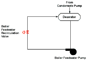
Figure 1 shows a typical feedpump recirculation system. The feedpump recirculation valve takes feedwater from the boiler feedpump discharge and recirculates it to the deaerator. The deaerator is typically located several stories above the feedpump to provide the necessary head to drive the pump. Depending on the size and type of plant, the valve may be reducing an inlet pressure of as high as 5500 psig to outlet pressures of about 150 psig. These extremely high pressure drops cause very high energy cavitation that will destroy a standard trim control valve in a very short time. In some plants, the recirculation line runs to the condenser, which provides an even higher pressure drop for the valve to handle that causes the valve to handle both cavitation and flashing conditions.

Figure 1: Boiler Feedpump Recircualation
There are three basic methods of providing feedpump recirculation. Each method employs a little different philosophy.
1. The modulating type of BFPR valve provides the most efficient method of recirculating. For each boiler feedpump, the manufacturer publishes a pump curve on which the required Net Positive Suction Head (NPSH) is given. For each power plant, there is a certain Net Positive Suction Head available as a function of the actual plant design and layout. To prevent cavitation from occurring in the pump, the NPSH available must be above the NPSH required. Therefore, the BFPR valve modulates to provide the minimum amount of feedwater to the feedpump to insure that the NPSH available is above NPSH required.
2. An on/off method of recirculation provides a constant amount of feedwater flow to the feedpump, up to a specified plant load, at which time the BFPR valve will close. This on/off valve service is less efficient than the modulating recirculation, because some energy is wasted since feedwater is recirculated at higher plant loads.
3. Continuous recirculation might be found in an older power plant. This method recirculates a certain amount of feedwater regardless of plant load, feedwater pressure or feedwater temperature. Since most feedpumps only require recirculation at low load conditions, this method of recirculation is the most inefficient since excess recirculation is lost energy. Also, since a certain amount of feedwater is always being recirculated, the feedpump will never obtain its maximum rated output capacity.
Fisher’s recommendation for the BFPR valve depends on the pressure drops involved. For drops less than 3000 psi, an appropriate size and pressure class HPT or EHT with two- or three-stage Cavitrol III trim may be used. Characterized trim should not be used since the pressure drop is relatively constant regardless of flow.
For pressure drops up to 3500 psi the design CAV4 three-stage or the Cavitrol III four-stage trim installed in an appropriate size HPT or EHT can be used. The Cavitrol III four-stage trim has actually been designed to provide cavitation protection up to pressure drops of 4000 psi. For pressure drops greater than 4000 psi, a CAV 4 with Cavitrol IV trim is used. Typically, a 2” or a 4” valve is needed. The Design CAV 4 is the most proven valve on the market for these extreme conditions. At these high-pressure drops, the quality and care of seating surfaces is very important. Tight shutoff can be provided by use of metal seats, which are “soft” and easily deformed and by the use of Tight Shutoff Trim (TSO). These soft seats avoid energy loss and provide longer trim life due to the elimination of wire-draw effects.
For dirty feedwater applications, the Dirty Service Trim (DST) has been used to allow the passage of particulates and still provide cavitation protection. The DST has been designed to provide cavitation protection up to pressure drops of 4500 psid and still allow the passage of particulates up to three-quarter inch in diameter. This is a very common problem in older power plants that have issues with pipe scale.
The feedpump recirculation application is a very demanding service, but by using the correct control valve with the appropriate cavitation protection the owner can be sure of proper pump protection. With the additional of tight shutoff technologies, one can be sure that there will not be any loss in efficiency due to a leaking valve.
|