|
Heater Drain
Application Discussion
AD106
June 15, 2003
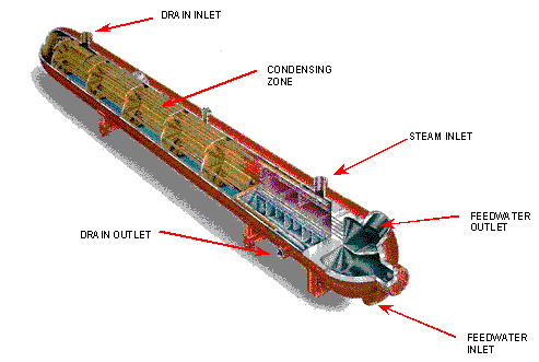
In order to prevent thermal shock caused by cold feedwater and improve unit efficiency, feedwater heaters are used to heat the incoming feedwater prior to flowing through the economizer section of a boiler. For example, by increasing the feedwater temperature by ten degrees, the unit efficiency increases by one percent. This is accomplished by using extraction steam pulled from the high, intermediate and low pressure sections of the steam turbine. The condensate from each heater has a considerable amount of energy and is also used to heat the incoming feedwater. Figure 1 shows a cross section of a shell and tube heat exchanger that utilizes both steam and the successive heater drains.

Figure 1: Shell & Tube Heat Exchanger
A cascading heater arrangement is the most common type of heater arrangement found in a power plant. These rely on extraction steam that is at or very near saturated conditions to heat the incoming feedwater. The condensate formed from the heating action is still at saturated conditions and is then sent to the next heater. A control valve is used to maintain heater level and will cause the draining condensate to flash, which increases the efficiency of heat transfer.
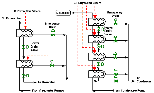
In a power plant, there are two sets of feedwater heaters. Low pressure heaters use extraction steam pulled from the low pressure turbine and are located after the condensate pumps. The condensate is routed through the low pressure heaters into an open heater called a deaerator. In the deaerator, the heating action drives off gases that can become corrosive to piping and associated equipment at elevated temperatures. The deaerator provides the suction for the main boiler feedpumps, which sends the feedwater through a series of high pressure heaters prior to the economizer that are fed by extraction steam from the high and intermediate pressure turbines. Figure 2 shows the high pressure and low pressure heater arrangement.

Figure 2: HP and LP Heater Arrangement
There are two valves that must be addressed on each heater. These are the normal heater drain valves and the emergency or high level dump drain valves. Both of these valves can dramatically affect unit efficiency. Studies have shown that many heater drain systems control very poorly and can cost a plant between 0.5 and 5 MW in performance. This is directly related to level control in the heaters, which is the responsibility of the normal heater drain valve.
The normal heater drain valve is used to control the condensate level in the heater and the flow of condensate to the next successive heater. As stated above, the incoming condensate is under saturated conditions. As the condensate passes through the valve, the condensate flashes to steam to aid in the heat transfer process. Flashing of steam can lead to severe erosion effects due to the high velocity steam carrying entrained water droplets.
The emergency heater drain can have a similar impact on unit performance. This valve is used only on high level alarms, therefore, tight shutoff is necessary to ensure proper performance. Any condensate that leaks through the valve will go directly to the condenser, which requires additional extraction steam to provide the proper heating. With the outlet flow going directly to the condenser, flashing will occur during valve operation.
In order to combat the flashing damage while providing proper control, Fisher recommends the use of an angle valve with a downstream liner. Since flashing is directly related to the downstream pressure, there is no way to eliminate it from occurring. Therefore, it is necessary to protect the valve and associated equipment from any of the damaging effects. The angle valve design directs the flow into the center of the valve away from the valve body and downstream pipe walls. The outlet liner is typically made of 440C materials and will resist any flashing fluid that may impinge on the valve body.
Globe valves can also be used, but it is recommended that the valve bodies be made of a chrome-moly material such as WC9. These types of materials, used in conjunction with hardened trim materials, will resist any erosion damage and subsequent control problems. It is also recommended to use a type EW valve body. The expanded ends reduce the velocity in the valve body and any subsequent erosion.
Another alternative is the use of a rotary valve solution. The Fisher type V500 with hardened trim flowed in the reverse direction has provided excellent results. The reverse flow reduces any erosion in the valve body and line size bodies lower the outlet velocity limiting erosion effects at the valve outlet and downstream piping.
Tight shutoff is a necessity for these applications to protect the integrity of the valve trim. The normal heater drain should be supplied with tight shutoff for situations where the heater is bypassed and leakage between heaters is possible. Since the emergency drain valves remain closed during normal operation, at a minimum Class V shutoff should be supplied. Tight shutoff will ensure that damage such as wire draw will be prevented. Heater efficiency will also be maintained as the warm condensate will not be lost to the condenser and additional extraction steam will not have to be taken from the turbine.
|