 |
||||||||||||||
|
BW240 Flashtank Pressure
Application Discussion Operation of a Babcock and Wilcox (B&W) Universal Pressure (UP) once-through boiler requires that a minimum flow be established in the furnace waterwalls prior to firing of the boiler. This is to prevent overheating of the boiler tubes during initial operation. This requires the use of a bypass system that is integral with the main steam, condensate and feedwater systems so that the minimum flow can be maintained at startup and at times when the required minimum flow exceeds turbine demand. The bypass system also performs the following additional functions: • Reduces the pressure and temperature of the steam leaving the boiler during startup to conditions that are suitable for the flash tank, condenser and auxiliary equipment. • Provides a way of recovering heat from the feedwater that flows to the bypass system by utilizing the feedwater heaters. • Provides a means for conditioning the water during startup without delaying boiler and turbine warming operations. • Protects the secondary superheater against thermal shock from water during startup. • Provides a means for relieving excess pressure in the boiler during a load trip. With these functions in mind, B&W developed a bypass system that routes water from the main boiler feedpumps back to the flash tank during startup of the unit. Figure 1 shows a common startup configuration that includes the BW240 valve. This valve has a number of functions that are discussed below.
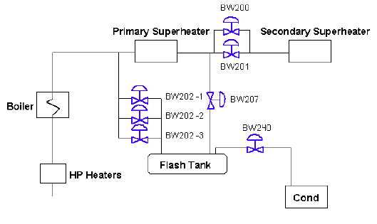
Figure 1: B&W Startup System Including BW240 During what is called the cold cleanup mode of operation, the superheater bypass valves are set to maintain 600 psig at the outlet of the primary superheater. The flow is bypassed from the primary superheater inlet to the flash tank. This occurs until the water chemistry is brought to a predetermined level when firing of the boiler begins. Once firing is initiated in the boiler and the temperature of the steam leaving the primary superheater reaches 300 degrees, the BW240 is opened to limit flash tank pressure to 500 psig. The steam from the flash tank is routed from the flash tank to the condenser, which is under a vacuum. After the flash tank pressure reaches 500 psig, the turbine can be rolled. After this occurs, the flash tank pressure rises to 1000 psig. The BW240 valve is then set to maintain 1000 psig in the flash tank and the turbine is ramped to seven percent load. As the unit load begins to reach 18 – 25 percent, the startup system begins to shut down. Once transfer to once-through operation is complete, the BW240 is closed and remains closed unless an over pressure situation occurs in the flash tank. Because of the high pressure drop through this valve the damaging effects of noise and vibration must be taken into account. Fisher recommends the use of the Whisper III trim in the appropriate EW or EU valve body. Valve sizes range between 8” and 12” depending upon unit capacity and the number of valves in the system. Since this valve is required to remain closed during normal operation, tight shutoff is recommended. Depending on valve construction this can be accomplished by using the high temperature version of the proven Omni-seal design. This design utilizes the Omni-seal with PEEK backup rings that prevent the PTFE from extruding at temperatures above 450 degrees. In larger valve constructions, the Fisher design C-seal is used. The C-seal utilizes a pressure assisted metal seal coupled with the normal metal to metal seating arrangement to provide tight shutoff at temperatures up to 1100 degrees. Both designs provide ANSI Class V shutoff and will eliminate any lost energy to the condenser. These tight shutoff technologies also protect the valve against any damaging erosion that can occur when not enough seating force is applied. |
|
|||||||||||||

