 |
||||||||||||||
|
Deaerator Pegging Steam
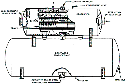
Application Discussion In order to remove corrosive gases entrained in boiler feedwater an open feedwater heater called a deaerator is incorporated into the power cycle. The deaerator is designed to heat the incoming feedwater to the saturation point in order to reduce the solubility of any entrained gases. These are mainly oxygen, carbon dioxide and ammonia that become very corrosive at elevated temperatures. Since main steam temperatures can reach as high as 1050 degrees, it is necessary to remove these gases to protect piping and associated equipment. Figure 1 shows the cross section of a typical deaerator. In this design, the incoming feedwater is pumped from the condensate pumps through the low pressure heaters. The water is sprayed in a fine mist into the area that substring the steam drawn from the high pressure heater drain and extraction steam from the cold reheat section. This divides the water droplets increasing the overall surface area therefore increasing the overall heat transfer. The water is then passed over a set of trays that separates the water into thin sheets from which the gas can easily escape. The gases are then vented out of the deaerator to the atmosphere.
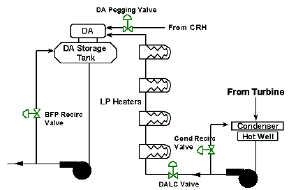
Figure 1: Cross Section of Deaerator The deaerator is located as high as possible in a plant to provide the suction for the boiler feedpumps. This can be as high as 60 feet in combined cycle plants and 120 feet in conventional fossil fuel plants. By placing the deaerator as high possible the need for booster pumps in conjunction with the boiler feedpumps is eliminated. In order to ensure mixing in the deaerator and the elimination of corrosive gases the level of incoming feedwater and steam must be properly controlled. The water level is controlled by what is commonly referred to as the Deaerator Level Control Valve or DALC valve. The steam is controlled through the heater drain valves and what is called the DA steam pegging valve. The source of the pegging steam varies by plant design. Some plants utilize steam from the cold reheat line while others use main steam or auxiliary steam. Figure 2 shows a common layout including the condensate pumps and LP heaters.
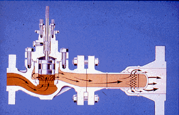
Figure 2: Process Flow Diagram Including DA Pegging Valve and Associated Equipment Valve selection for this application varies by plant design and will depend upon the source of the pegging steam. One of the most common extraction points is the exhaust steam from the high pressure turbine, which is referred to as cold reheat steam (CRH). The steam pressures vary between 300 and 600 psig with temperatures ranging from 450 to 550 degrees. Since the DA operates under minimal pressures the pegging valve must handle nearly a full pressure drop. With high pressure drops comes the possibility of excessive noise that can lead to pipe vibration and damage to downstream equipment. Depending upon the source of pegging steam Fisher recommends the use of Whisper I or Whisper III noise abatement trim to control the noise. Another common solution is the use of a downstream diffuser or sparger in combination with a control valve as seen in Figure 2. This device emits a back pressure on the control limiting the pressure drop across the valve and subsequent noise formation.
Figure 2: Valve with Downstream Diffuser for DA Pegging Service As with any severe service application, tight shutoff is recommended. This protects the valve from damage due to leakage in the closed position while also maintaining unit efficiency. This can be accomplished with a number of solutions, but with the temperatures experienced in this application the Fisher C-seal is the most common. |
|
|||||||||||||


